Teleoperation to Obstacle Sensing
March 2018
 |
|---|
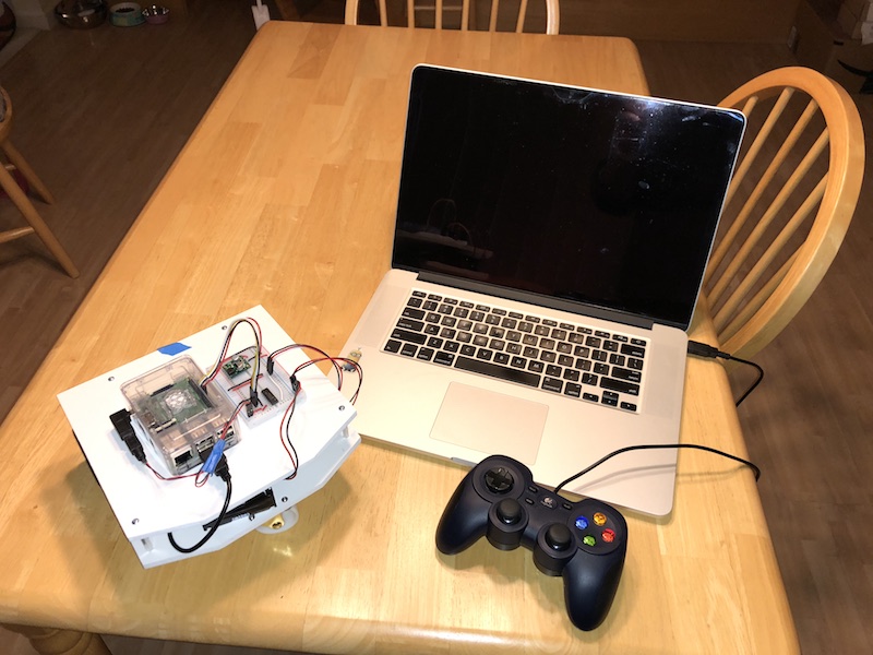
| B2’s teleoperation setup |
Teleoperation testing
In the original design, I planned to have the drive wheels in the rear with the caster in the front (a RWD robot). You can see that in the Fusion 360 design and the picture above where I made a stylistic bevel to the front edge (caster side) and left the rear edges square. My idea was that if the caster hit an obstacle on the floor, the resistance would cause more pressure on the rear wheels, thus providing more traction for the drive wheels allowing it to drive over the obstacle.
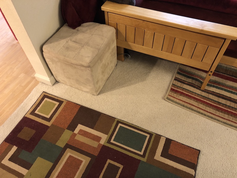
But when testing using the joystick and teleop_node I realized the caster gets stuck on our thicker area rugs and the rear wheel just spin without traction. However if I drove B2 in reverse over the carpet, it climbed right over the rug with no problems.
Therefore B2 is now a FWD robot!
 |
|---|
| Area rugs: B2’s archenemy |
Lesson learned: If you aren’t yet sure how your robot will work, don’t spend much time on cosmetic design. Else it might end up driving backwards like B2 does now.
Obstacle sensing
Having the base_node drive control and odometry logic sorted out, and tested using teleoperation, I moved on to building B2’s ability to sense its environment.
At first, B2 would simply use IR sensors to detect proximity to walls and other obstacles. This should be sufficient for its main goal as a hide & seek game robot.
However, B2 doesn’t really need odometry for that. So why did I put the effort into learning how to calculate odometry? Because my plan is to extend B2 beyond its original goal of hide & seek to do more interesting things around the house. For this B2 will need better sensors, and an ability to localize itself within the house. But that’s a later goal.
When Pololu had its Black Friday 2017 sale, I also picked up four Sharp GP2Y0A60SZLF IR sensors. These are analog sensors, so their output is an analog signal representing the distance to an object, not a digital signal. And since I used the Roboclaw instead of an Arduino, and the Raspberry PI 3 does not have any Analog-to-Digital Converters (ADCs) I needed a way to convert the analog signal to a digital one so it could be interpreted by a ROS node to send messages to the other parts of B2.
I found this great article by Adafruit that covered exactly what I needed:
Originally, I wanted to attempt to use the IR sensors to measure distance. But after wiring them up and testing them, I realized the output voltage curve is too exponential to be reliable as a measuring sensor. The voltage changes quickly as an object moves near the sensor, but if the object is at distance the voltage changes are very minor even for large distance changes. Therefore, I accepted that I must only use them as proximity sensors.
I created a ROS node (sensors_node) to read the output of the ADC chip over SPI from the Raspberry PI’s GPIO pins. It compares the ADC value to a threshold calculated from a distance goal. And it publishes the state of the proximity sensors as simply True or False, where True means there is an object in proximity.
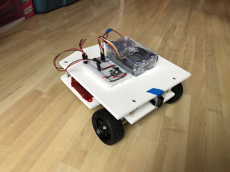
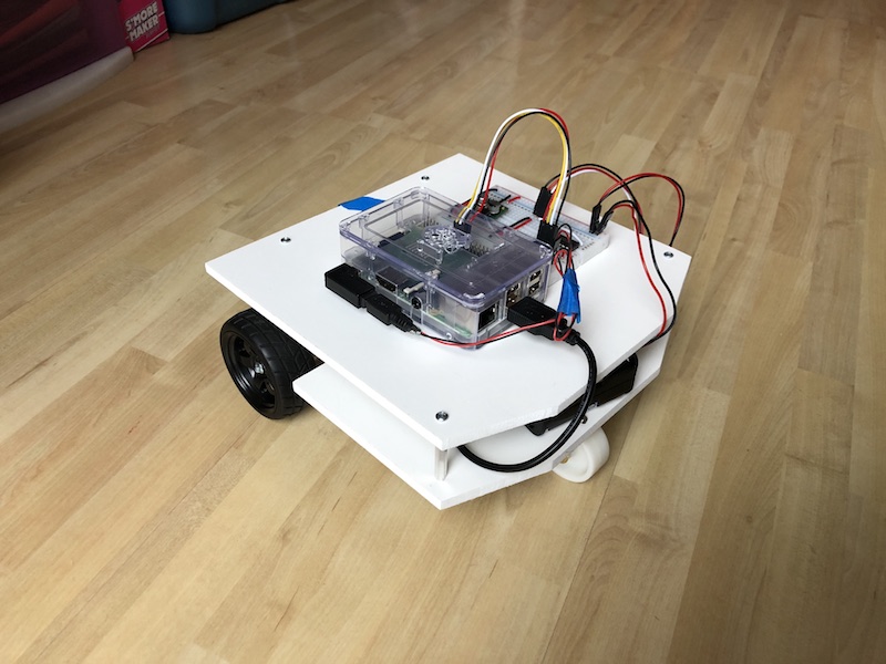
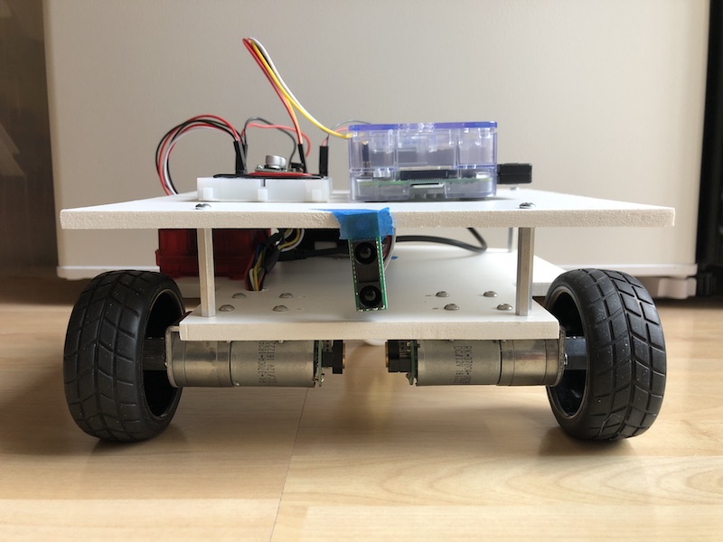
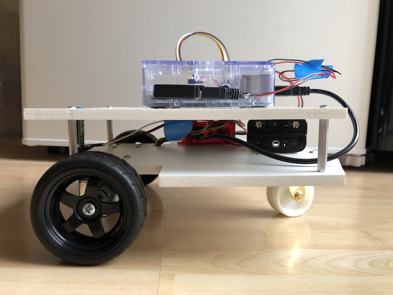
Below is what B2 looks like on 10 Mar 2018 - as the FWD robot.
 |
 |
|---|---|
| Front-Right | Rear-Left |
 |
 |
|---|---|
| Front | Side |
With B2 able to sense obstacles now, it’s time to move on to autonomous driving.